Executive Summary
Alloy 800H is a high-performance, nickel-iron-chromium alloy that is specifically designed for high-temperature service. Its composition and properties make it suitable for a range of demanding applications including pressure vessels, heat exchangers, and other process components. However, 800H has an inherent susceptibility to solidification cracking during fabrication because of its larger grain structure and alloying additions. In this case study, Alloy 800H (UNS N08810) forgings were welded with NiCr-3 filler metal. Microfissures were observed with dye penetrant inspection adjacent to the fusion line in the HAZ of the Alloy 800H base material. Experimentation was performed by varying weld processes, metal transfer, heat input, and shielding gas. Evaluation of the as-received and HAZ base material revealed large grain size and intergranular cracking, respectively. Minimal cracks were found with the SMAW, GTAW, and FCAW processes at low heat input, and cracks were eliminated only at extremely low weld heat inputs. The mill test reports for the forgings were analyzed to determine changes in chemistry, thermal history, and grain size, as compared to the previous heats. Silicon (Si) and titanium (Ti) had elevated readings but were still within specification. A sample containing a crack was removed and evaluated using scanning electron microscopy/ energy dispersive X-ray spectroscopy (SEM/EDS) technology and optical microscopy to examine the microstructure and to determine specific elements on the internal crack surface. After completion of this testing, along with other evaluations, research, and consultation, it was concluded that the microfissures were a result of a HAZ grain boundary liquation cracking mechanism caused by large grain size and elevated Si and Ti contents in the 800H forging base material.
Introduction
The weldability of Alloy 800H forgings was assessed because of concern about dye penetrant inspection indications adjacent to the fusion boundary of welds made with NiCr-3 filler metal. Alloy 800H is a crucial component material utilized in pressure vessels. The weldability was examined by performing several test welds varying weld processes, metal transfer, heat input, weld location, filler metal, base metal thermal history, and shielding gas. In addition, replications were applied to the base material, along with the weldment, to evaluate the microstructure and cracking through optical microscopy. A sample containing microfissures in the 800H HAZ was obtained and analyzed using microscopy and SEM/EDS technology to determine the elemental composition on the crack surface.
Alloy 800H Forging Material
The Alloy 800H (UNS N08810, ASME SB564, P-No. 45) forging material and NiCr-3 (UNS N06082, ASME Section IX F-No. 43) filler metal nominal compositions are listed in Figure 1. The material has a nickel-rich face-centered cubic (fcc) austenitic microstructure, which is solid-solution strengthened with alloying additions. Alloy 800H is typically solution annealed between 1950 to 2150°F to assure that alloying additions are dissolved in the austenite matrix and to eliminate any embrittling phases. The forgings supplied were heated at 1800°F for six hours, and water was quenched by the manufacturer. In the ASME SB564 specification for nickel alloy forgings, the average grain size requirement is an ASTM No. 5 or coarser.
In the 800H heat-affected zone, several metallurgical reactions can occur, including grain growth, grain boundary segregation, and grain boundary liquation. Alloying additions, such as Ti and Si, and impurity elements like S and P, can segregate to grain boundaries upon heating. This segregation can form low melting point eutectic constituents along the grain boundaries. For example, during welding, the base metal just adjacent to the fusion zone will experience a range of temperatures which are between the liquidus and the effective solidus temperature of the 800H alloy. In this region, partial melting, or liquation, will occur at the grain boundaries forming low melting point eutectic films. Liquation cracks will form if the locally melted region cannot sustain the applied strain due to welding.
| Alloy/AWS Class | UNS No. | Material | Cr | Ni | Fe | Cu | Ti | Al | C | Mn | S | Si | Nb |
| 800H | N08810 | Forging | 19–23 | 30–35 | 39.5 min | .75 max | 0.15–0.60 | 0.15–0.60 | 0.05–0.10 | 1.5 max | 0.015 max | 1.0 max | — |
| ERNiCr-3 | N06082 | Filler | 18–22 | 67 min | 3.0 max | 0.50 max | 0.75 max | — | 0.10 max | 2.5–3.5 | 0.015 max | 0.50 max | 2.0–3.0 |
Figure 1. Base Metal/Filler Metal Composition
Experimentation and Results
There have been several attempts to eliminate the cracking indications in the 800H forging material. The first action was to reduce weld heat input and HAZ base metal strain. This was attempted by adjusting weld parameters and experimenting with different welding processes. Figure 3 lists the testing that was performed along with the results. Six different welding processes were used, which included SMAW, FCAW, GTAW, GTAW-P, GMAW, and GMAW-P.
In addition, welding parameters were varied to increase and decrease heat input. Changing of filler metals between NiCr-3, NiCrFe-3, NiCrMo-3, NiCrMo-4 and autogenous welding (no filler) were tested along with shielding gas changes between 99.997 Ar, 75/25 Ar/CO2, 75/25 Ar/He, 90/10 Ar/He, and 95/5 Ar/He. The results revealed that utilizing the GTAW, SMAW, or FCAW process at low weld heat input dye penetrant indications was minimized or eliminated.
The next possible solution was to heat treat the material. By solution annealing the 800H forging, the plan was to dissolve carbides which could cause cracking. This test was performed by heat treating two scrap discs (≈0.200″) obtained from the machining of the 800H forgings. The discs were held at 1950°F for 30 minutes then water quenched. GMAW-P fillet welds were made on the heat-treated disks. Dye penetrant inspection and stereo microscopic examinations were performed on the weldments. Indications were observed by penetrant inspection, and the stereo microscope images displayed cracks along the fusion zone as displayed in Figure 2.
| Alloy 800H Weld Tests | ||||||||
| Weld # | Base Pos. | Process | Current(A) | WFS(ipm) | Voltage(V) | Filler | Shield Gas | Indications |
| 1 | top side | GTAW | 200 | N/R | N/R | No Wire | 100Ar | no |
| A | side | GTAW | 200 | N/R | N/R | No Wire | 100Ar | no |
| 2 | top side | GTAW | 200 | N/R | N/R | No Wire | 100Ar | no |
| B | side | GTAW | 200 | N/R | N/R | No Wire | 100Ar | no |
| 3 | top side | Pulse GTAW | 200 | N/R | N/R | No Wire | 100Ar | yes |
| C | side | Pulse GTAW | 200 | N/R | N/R | No Wire | 100Ar | yes |
| 4 | top side | Pulse GTAW | 200 | N/R | N/R | ERNiCr-3 | 100Ar | some |
| D | side | Pulse GTAW | 200 | N/R | N/R | ERNiCr-3 | 100Ar | some |
| 5 | top side | Pulse GTAW | N/R | N/R | N/R | ERNiCr-3 | 100Ar | some |
| E | side | Pulse GTAW | N/R | N/R | N/R | ERNiCr-3 | 100Ar | some |
| 6 | top side | GTAW | N/R | N/R | N/R | ERNiCr-3 | 100Ar | no |
| F | side | GTAW | N/R | N/R | N/R | ERNiCr-3 | 100Ar | no |
| 7 | top side | SMAW | 110 | N/R | N/R | ENiCrFe-3 | N/A | no |
| G | side | SMAW | 110 | N/R | N/R | ENiCrFe-3 | N/A | some |
| 8 | top side | Pulse GMAW | N/R | N/R | N/R | ERNiCr-3 | 75Ar/25He | some |
| H | side | Pulse GMAW | N/R | N/R | N/R | ERNiCr-3 | 75Ar/25He | some |
| 9 | top side | Spray GMAW | N/R | N/R | N/R | ERNiCr-3 | 100Ar | some |
| I | side | Spray GMAW | N/R | N/R | N/R | ERNiCr-3 | 100Ar | some |
| 10 | top side | FCAW | 170 | 355 | 25.6 | ENiCr-3 | 75Ar/25CO2 | no |
| J | side | FCAW | 170 | 355 | 25.6 | ENiCr-3 | 75Ar/25CO2 | no |
| 11 | top side | FCAW | 170 | 355 | 25.6 | ENiCrMo-3 | 75Ar/25CO2 | no |
| K | side | FCAW | 170 | 355 | 25.6 | ENiCrMo-3 | 75Ar/25CO2 | no |
| 12 | top side | Spray GMAW | 204 | 275 | 27 | ERNiCrMo-3 | 100Ar | yes |
| L | side | Spray GMAW | 204 | 275 | 27 | ERNiCrMo-3 | 100% Ar | yes |
| 13 | top side | Pulse GMAW | N/R | 355 | N/R | ERNiCrMo-3 | 75Ar/25He | yes |
| M | side | Pulse GMAW | N/R | 355 | N/R | ERNiCrMo-3 | 75Ar/25He | yes |
| N | side | Pulse GMAW | N/R | 355 | N/R | ERNiCrMo-3 | 75Ar/25He | yes |
| O | side | Pulse GMAw | N/R | 355 | N/R | ERNiCr-3 | 95Ar/5He | yes |
| P | side | Pulse GMAW | N/R | 355 | N/R | ERNiCr-3 | 90Ar/10He | yes |
| Q | side | Pulse GMAW | 197 | 355 | 25.6 | ERNiCr-3 | 100Ar | yes |
| R | side | Pulse GMAW | N/R | 355 | N/R | ERNiCrMo-4 | 75Ar/25He | yes |
| S* | side | Pulse GMAW | 216 | 355 | 26.5 | ERNiCr-3 | 100Ar | yes |
| T | side | Spray GMAW | 165 | 275 | 24 | ERNiCr-3 | 100Ar | yes |
| U | side | Spray GMAW | 167 | N/R | 26 | ERNiCr-3 | 90Ar/10He | yes |
| V | side | Spray GMAW | 155 | N/R | 25.5 | ERNiCr-3 | 95Ar/5He | yes |
| W | side | Spray GMAW | 167 | N/R | 26 | ERNiCr-3 | 95Ar/5He | yes |
| X* | side | Spray GMAW | 275 | N/R | 29 | ERNiCr-3 | 100Ar | yes |
| Y | side | FCAW | 160 | N/R | 25.3 | ENiCrMo-3 | 75Ar/25CO2 | no |
| Z | side | FCAW | 160 | N/R | 25.3 | ENiCr-3 | 75Ar/25CO2 | no |
| N/R = not recorded *Performed with Thermal Arc Welder | ||||||||
Figure 3. Weld Testing
Analysis and Discussion
By analyzing the results from the testing, preliminary conclusions could be drawn to develop future investigation. Because the indications were detected directly after welding and because of the inherent characteristics of the material, it was determined that a type of solidification cracking was the issue. In addition, the results proved that low weld heat input minimized or even eliminated the indications. Lowering heat input in welds, in turn, increases the cooling rate, reduces strain on the 800H material, and permits less time for low melting point segregates to migrate to the grain boundaries, thus minimizing grain boundary liquation.
After considering the results from the testing, an investigation of the solidification cracking was performed by analyzing the 800H forging material and examining the HAZ of the weldments. This investigation included base metal grain size detection, stereo and optical microscopy, and SEM/EDS analysis. In addition, a comparison of the compositions of each heat was graphed to detect any trends in crack susceptibility with elevations in specific elements.
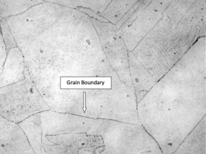
The grain size detection was performed by evaluating replications created from the as-received base metal. The evaluation was completed with an optical microscope by the comparison method. The ASTM nominal grain size number was found to be 2 to 0, with 0 being the largest. This is a coarse grain size but it’s still within specification (ASME SB564). Figure 4 displays one of the micrographs of the replication from which the grain size was identified. Although this is within ASME code, this could cause weldability issues. As the grains of a material increase, the grain boundary area decreases, thus increasing the applied strain on each grain boundary during welding. Also, the decrease in grain boundary area will increase the concentration of impurity, and low melting point segregates at the grain boundaries on heating, making the material more susceptible to HAZ liquation cracking.
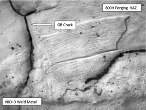
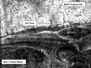
Replications were also created from the HAZ of a weld made on the 800H forging. They were examined with optical microscopy. Figures 5 and 6 reveal the HAZ solidification cracking directly adjacent to the fusion line. Through these micrographs, it was evident that the microfissures were located in grain boundaries of the heat-affected zone and, more specifically, in the partially melted zone (PMZ). The PMZ is the area immediately adjacent to the weld metal where liquation of the grain boundaries in the base metal can occur during welding. Because the replications only copy the topography of the surface, SEM/EDS analysis could not be performed. Consequently, a sample containing the actual HAZ of the 800H material needed to be removed so a thorough examination of the microfissures could be conducted.
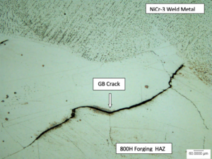
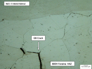
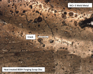
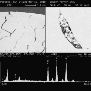
A small sample from the HAZ of an FCAW fillet weld made on the 800H forging was removed for evaluation. The sample was mounted, polished, and etched to reveal the microstructure and microfissures. Figures 7 and 8 display the micrographs captured with optical microscopy. In addition, scanning electron microscopy/ energy dispersive X-ray spectroscopy (SEM/EDS) analysis was utilized for further examination. Figure 9 displays the SEM image and the EDS analysis of the composition found in one of the HAZ microfissures. This analysis proved that Silicon (Si), an element that forms a low melting eutectic constituent, was present in the crack.
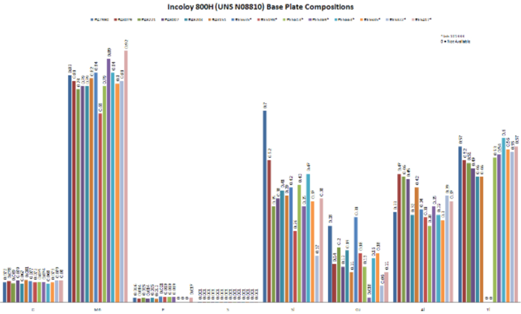
The heat of 800H forging material that was used for the SEM/EDS analysis produced more microfissure indications than any other heat of the forging material. Due to this consideration, a comparison of the compositions of each heat was graphed to detect a trend in crack susceptibility and elevations in specific elements.
This graphical analysis is displayed in Figure 10. By comparing the data, it is evident that the silicon content, 0.70 wt %, in heat 47980 is higher than any other heat. In addition, the titanium content, 0.57 wt %, is relatively elevated as compared to the other heats. Silicon and titanium are two of several elements that form low melting point eutectic constituents. During welding, these elements can segregate to the grain boundaries and form liquid films in the PMZ. If sufficient stress is present and the grain boundary cannot sustain the applied strain because of the liquid film, grain boundary liquation cracking will occur.
Conclusion
After experimentation and analysis, it is determined that the mechanism responsible for causing the microfissures is a type of solidification cracking known as grain boundary HAZ liquation cracking. This is a direct result of the alloy 800H forging material. The forging material has an inherent susceptibility to solidification cracking, especially when coupled with its large grains and alloying additions.
Specific heats of the base plates have relatively high amounts of elements, particularly Si and Ti, which can form low melting point eutectic constituents. During welding, these constituents form liquid films at the grain boundaries of the base metal directly adjacent to the fusion zone, specifically in the partially melted zone. Liquation cracking occurs when the grain boundary cannot sustain the applied strain and microfissures form. Because liquation cracking susceptibility is affected both by alloying composition and the condition of the base metal, it is even more evident that liquation cracking is the mechanism because of the coarse grain size of the forging. Due to the large grains, the grain boundary area decreases, and the applied strain on each grain boundary increases. Also, the decrease in grain boundary area increases the concentration of impurity and low melting point segregates at the grain boundaries, making the material even more susceptible to HAZ liquation cracking.
Because of the alloy 800H forging susceptibility to grain boundary HAZ liquation cracking, the following recommendations are offered:
- Reduce the amount of Si and Ti contents by introducing a lower maximum limit while staying within specification.
- Restrict the grains to a finer grain size to increase grain boundary area while still complying with ASME SB564.
- Develop and initiate an inspection plan for vessels containing base plates with higher wt % of Si and Ti.
References
Kuo, Sindo, Welding Metallurgy, Second Edition, John Wiley & Sons, Inc. (2003)
DuPont, John N., Lippold, John C., Kiser, Samual D., Welding Metallurgy and Weldability of Nickel-Base Alloys, John Wiley & Sons, Inc. (2003)
Lippold, John C., Kotecki, Damian J., Welding Metallurgy and Weldability of Stainless Steels, John Wiley & Sons, Inc. (2005)
ASME 2023 Section II, Part B, SB 564, “Specification for Nickel Alloy Forgings”